
State diagrams
State machine diagram are usually implemented to describe state-dependent behavior for an object. An object responds differently to the same event depending on what state it is in. That means that it is important to define the state that you object is in to accurately predict its behaviour.

© Visual Paradigm https://www.visual-paradigm.com/guide/uml-unified-modeling-language/what-is-state-machine-diagram/
What is a state?
A state is an abstraction of the attribute values and links of an object. Sets of values are grouped together into a state according to properties that affect the gross behavior of the object.
Package diagram
In this technique each class is put into a single package. If a class wishes to use another class in the same package, all is well. If a class wants to use a class in a different package it must draw a dependency to that package. The overall picture of the system is the picture of packages and their dependencies, the aim is to keep the dependencies down to a minimum.

© Department of Computer Science. University of North Carolina at Chapel Hill
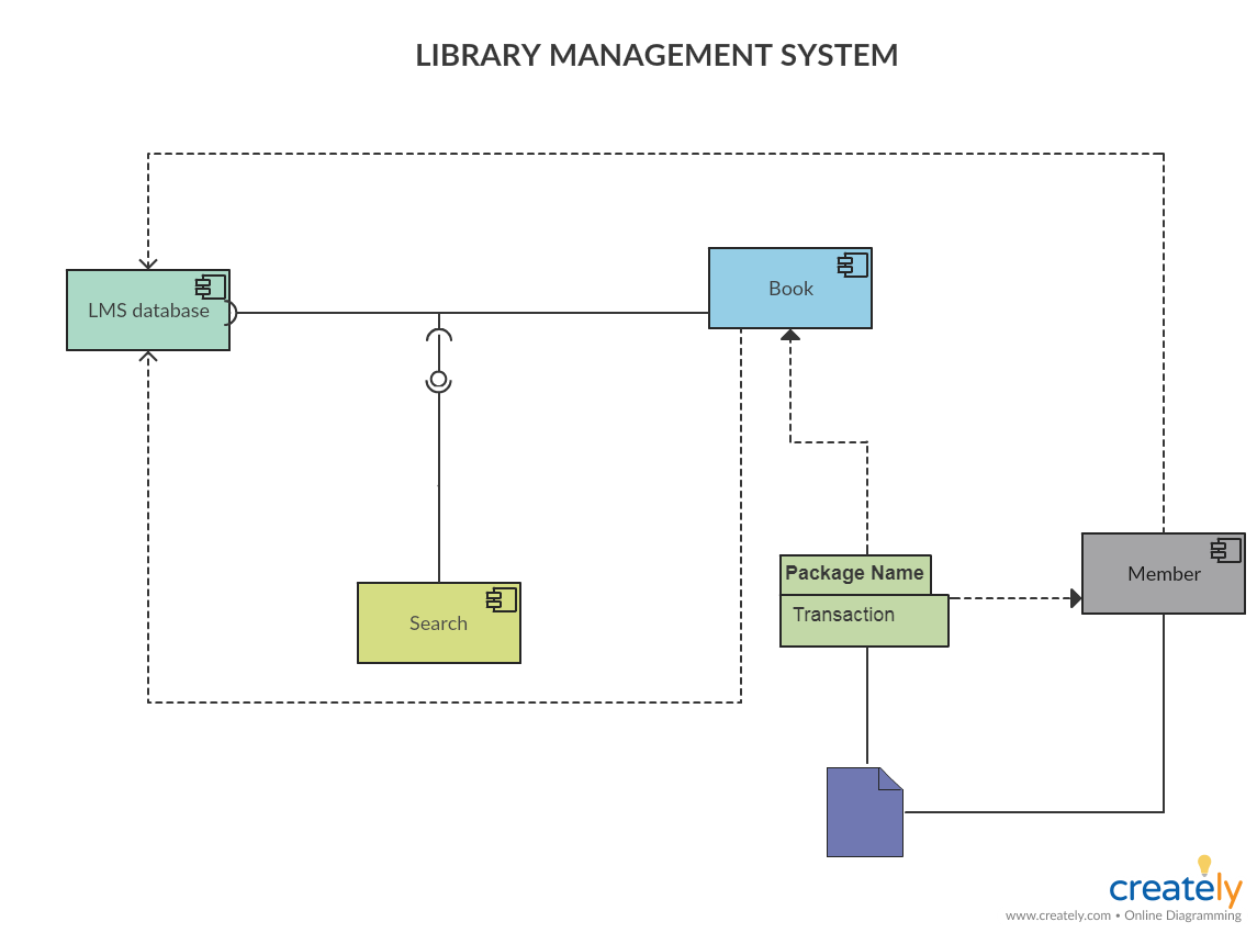
Component Diagram
Component diagrams are used to visualize the organization of system components and the dependency relationships between them. They provide a high-level view of the components within a system.
What is a component?
The components can be a software component such as a database or user interface; or a hardware component such as a circuit, microchip or device; or a business unit such as supplier, payroll or shipping.
References
http://www.cs.unc.edu/~stotts/145/CRC/package.html
https://www.visual-paradigm.com/guide/uml-unified-modeling-language/what-is-state-machine-diagram/
https://creately.com/blog/diagrams/component-diagram-tutorial/
